How Does A 3 Wire Proximity Switch Work
3-Wire and 4-Wire DC Inductive Proximity Sensors 3-Wire and 4-Wire DC 89 2-Meter Cable Models Dia. Two power wires and one load wire.
Two Wire Inductive Proximity Sensors The Universal Donor
Send a fluctuating electric current through a coil of copper wire and although you cant see it happening youll produce a temporary magnetic field around the coil too.

How does a 3 wire proximity switch work. Normally Open sensor will work Normally Open Wiring Diagram for NPN and PNP 3 wire sensors with the DND TECHNOTES Product group. Our Cylinder Inductive Proximity Sensors are used for end-of-stroke sensing of pneumatic and hydraulic cylinders or for openclosed indication on power clamps and grippers. Two power wires and one load wire.
A three-wire sensor has 3 wires present. 3 kHz SS PUR22 AWG 1 NBB2-12GM50-E0 2 Flush NPN NO. 2 The blind zone of an ultrasonic proximity sensor can be from _____ - _____ cm depending on the sensor.
It is simply two wire circuit coming from Digital input module. 12 NJ2-12GM40-E2 2 Flush PNP NO. 2 wire sensor is basically a loop-powered device without requiring a separate supply voltage the source voltage is supplied to the destination device whereas the 3 wire sensor is a self-powered device meaning you supply source voltage to the sensor and it can drive a 4-20 ma input device directly without the destination device requiring any supply voltage.
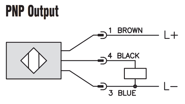
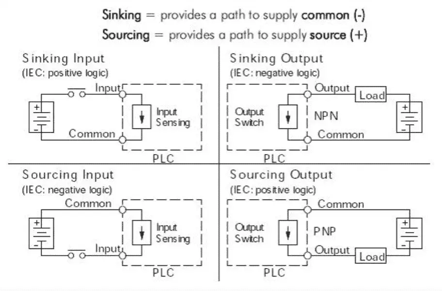
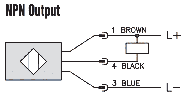
16 point DC input module. Either the load is connected to Negative and the P ositive is switched P NP or the. P NP Switched P ositive.
Switched refers to which side of the controlled load relay small indicator PLC input is being switched electrically. 3 The approximate angle of the main sound cone of an ultrasonic proximity sensor. These output wires are run straight to a modules input.
15 kHz Ni-Brass PVC26 AWG 2. Mm Model Number Range mm Mounting Electrical Output Switching Frequency Barrel Material Cable JacketSize Dwg. Put the coil near to a big permanent magnet and the temporary magnetic field the coil produces will either attract or repel the magnetic field from the permanent magnet.
Many proximity switches though do not provide dry contact outputs. When using inductive proximity sensors for a control application it is common to choose a 3-wire DC prox that has a dedicated NPN or PNP control output and bring the output into a PLC input. Wiring Instructions for the MICRO SWITCH VPX.
Choosing between polarities means determining how the common is wired and selecting accordingly. They sense the presence of metal objects-ferrous and nonferrous-without touching them. Its -ve should be from DCS power supply.
1 Ultrasonic proximity sensors use high frequency _____ signals to detect the presence of a target. How does a 3 wire proximity sensor work. A three-wire sensor has 3 wires present.
Our Tubular Inductive Proximity Sensors are self-contained solid-state switching devices. If the inductive Proximity sensor is wired incorrectly. The power wires will connect to a power supply and the remaining wire to some type of load.
The power wires will connect to a power supply and the remaining wire to some type of load. Input cards do not know the difference between 2- 3- or 4-wire sensors but input cards for 2-wire sensors must be rated to accept the sensors voltage drop and off-state current level noted on datasheets Sensors with 3 and 4 wires have dedicated output wires. Heres a simple way remember how to wire up a 3-wire DC PNP or NPN sensor.
The only confusion is that for 2 wire proximity one of the wire from DCS gives the return path for positive 24 Vdc but in 3-wire how will we take the return path if there are three wires in the field and the instrument is passive ie. When a target the object that a sensor is detecting comes within sensing range of the sensor the sensor output turns on and current flows. The sensor LED will stay ON and go OFF when activated.
Proximity Switches Working PrincipleProximitySwitch ProximitySwitchPrinciple ProximitySwitches. Normal proximity switches use a permanent magnet so it can create a sealed switch mechanism if an objects mechanical part come close to it. The schematic diagram symbol for a proximity switch with mechanical contacts is the same as for a mechanical limit switch except the switch symbol is enclosed by a diamond shape indicating a powered active device.
Proximity switches can detect the approach of a metallic device part with the help of a magnetic or electromagnetic field. N PN Switched N egative.

3 Wire Inductive Proximity Sensor How To Read The Datasheet Realpars

3 Wire Proximity Sensor Wiring Diagram Engineers Commonroom Youtube

Wiring 3 Wire Dc Npn And Pnp Sensors Acc Automation

3 Wire Inductive Proximity Sensor How To Read The Datasheet Realpars
Two Wire Inductive Proximity Sensors The Universal Donor

Wiring 3 Wire Dc Npn And Pnp Sensors Acc Automation

Proximity Sensor Working Principle Proximity Sensor Wiring Npn And Pnp Youtube

3 Wire Inductive Proximity Sensor How To Read The Datasheet Realpars
Post a Comment for "How Does A 3 Wire Proximity Switch Work"